During a heat-exposure or repeated-fit test, a printed enclosure may prove unsuitable despite looking accurate on a desk. Appearance, structural behavior, and dimensional acceptance are separate questions, even when they concern the same model.
A request for custom 3D printing services is most useful when it states what the printed part must demonstrate: visual form, assembly clearance, functional loading, or a short period of service. That test objective determines whether the build method, material, and post-processing route are appropriate.
Define What the Printed Part Must Prove
A concept model may need only recognizable form and accessible fastening locations. A working fixture, by contrast, may require stiffness, predictable clamping surfaces, and resistance to its operating environment.
Before pricing, the specification can identify load direction, temperature exposure, required surface condition, and the dimensions used to judge fit. Cosmetic approval and functional validation should not be treated as interchangeable evidence merely because both rely on a physical sample.
The 3D model also needs an honest description of its smallest features and inaccessible cavities. Internal channels can be difficult to clear of uncured resin or residual powder; narrow holes might require finishing rather than being accepted exactly as printed.
A useful build review links each questionable feature to a planned test or inspection method. If a thread or sealing face must meet a close dimensional requirement, subsequent machining may belong in the route from the outset.
Match the Printing Method to the Test
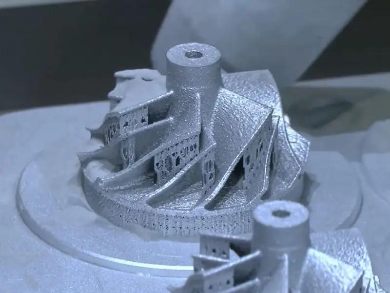
Three familiar additive processes create different material structures. SLA or DLP cures photopolymer resin and is suited to detailed models with relatively smooth surfaces. Selective laser melting, or SLM, fuses metal powder for metal components including complex internal passages.
FDM places thermoplastic filament in deposited paths and can produce larger fixtures and trial enclosures. A request for custom 3D printing services needs both a named process and a feedstock, because resin models, metal parts, and thermoplastic fixtures are evaluated against different material requirements.
Resin options can include tough ABS-like, clear, high-temperature, or flexible formulations; these labels still require the actual resin data for a performance test. Hanstar’s SLM material options include AlSi10Mg aluminum, stainless steels 316L and 17-4PH, and Ti-6Al-4V titanium.
FDM choices include ABS, PETG, PC, PA6/PA12 nylon, TPU, and reinforced polymers. The company’s approximate build envelopes are 600 × 600 × 400 mm for SLA, 400 × 400 × 400 mm for SLM, and 1,000 × 1,000 × 1,000 mm for FDM.
Account for Build Direction and Support Removal
A layer-based part does not behave exactly like a component cut from homogeneous stock. Orientation influences supported overhangs, visible layer patterns, and the direction in which a printed feature is loaded.
FDM parts, for example, may respond differently to loading across deposited layers than along their printed paths. Reorienting a model can address one concern while creating new supports or surface marks elsewhere. Orientation is consequently part of the engineering decision, not simply a preparation step in software.
Supports, uncured resin, or loose powder also have to be removed without damaging functional surfaces. A deep channel may be printable in principle yet difficult to clean or inspect afterward. Allowances for finishing are especially relevant at mating holes, threaded connections, and locating faces. Where a printed metal component requires close interfaces, a planned CNC operation can establish those features after the additive build instead of relying entirely on as-printed geometry.
Inspect the Finished Condition, Not Only the Build
Inspection conditions differ between as-printed features and CNC-finished interfaces. Typical dimensional tolerances for Hanstar’s printing processes are about ±0.1 mm for SLA, around ±0.1 mm on smaller SLM features, and approximately ±0.3 mm for FDM, with actual outcomes dependent on geometry and dimensions. These are not universal guarantees. A larger enclosure, thin lattice, and small mating boss may each need different acceptance checks, particularly after support removal or surface finishing.
Additive operations at Hanstar Technologies cover SLA/DLP, SLM, and FDM for prototypes and low-volume industrial parts. Suitable printed-metal bores, threads, and mating faces can receive secondary CNC machining, with selected quoted machined dimensions down to ±0.01 mm under appropriate conditions.
Coordinate measurement, inspection reports, and material certificates can be discussed where the order requires them. The test result should refer to the final delivered state, including any post-machining, rather than to an intermediate build still awaiting finishing.
Decide What Happens After the Trial
A validated printed prototype does not necessarily establish the best route for repeated production. Expected volume, material properties, finish requirements, and the risk of design changes may favor continued printing or a transition to CNC machining or molding.
Hanstar Technologies accepts additive orders starting from a single piece with indicative post-confirmation lead times of two to four business days for FDM, three to five for SLA, and five to eight for SLM, subject to job requirements.
An inquiry stating intended use, material target, critical interfaces, and test acceptance criteria gives the printing job a measurable purpose. The scope of custom 3D printing services can distinguish the raw build from support removal, any planned CNC finishing, and final inspection. A short test brief accompanying the model gives Hanstar Technologies the basis to discuss a suitable printing process and inspection scope before the part is built.